
Fixed large inclination belt conveyor installation
12th April 2022
Scope of application:
This standard is applicable to the installation and management of various types of belt conveyorsand their safety facilities and protective devices that are mainly transported in mine roadways, up and down slopes in mining areas, and excavated working faces.
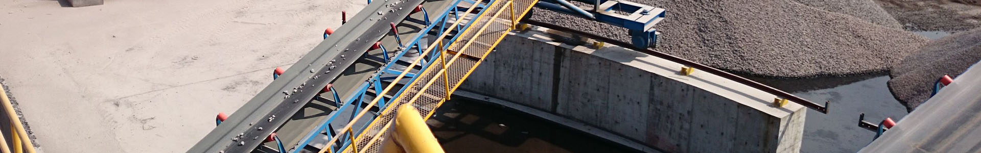
Belt conveyor installed well
(1) Machine head installation
1. The fixed belt conveyors of the main transport roadway and the mining area up and down the mountain should be based on concrete, and the belt conveyors of the mining face should be fixed with ground anchors. The magnetic head drive must be fixed firmly and reliably without shaking or shaking.
2. Concrete foundation standard: The foundation of the belt conveyor to be laid should be specially designed and constructed in strict accordance with the design requirements. It can be installed only after the joint acceptance of the production department, the mechanical and electrical department, the security inspection department and the construction unit.
3. Ground anchor setting standard: use Φ20×20m high-strength anchors with a diameter of not less than 30m and a length of not less than 1.5m or no less than 6 special ground anchors (3 on each side of the frame), which are vertically or slightly inclined. drive into the chassis. Use Φ15.5 steel wire rope or 40T (Φ18×64m) chain to fix the anchor rod and the frame firmly to ensure that the transmission part of the nose is straight and stable. Ground anchor tensioning direction: 4 in the direction of the head of the upper belt conveyor and 2 in the direction of the tail; the ground anchor setting of the lower belt conveyor is opposite to that of the upper belt type.
4. In principle, the drive device is arranged on one side of the sidewalk, which is convenient for installation and maintenance. The distance between the pedestrian side drive device and the roadway is greater than 70m, the distance between the non-pedestrian side drive device and the roadway is greater than 50m, and the distance between the discharge roller and the roof is not less than 60m.
5. When the tension trolley guide rail is installed, its gauge deviation is not more than 3mm, the track straightness deviation is not more than 3/100, the height deviation of the two rails is not more than 1.5/100, the track joint gap should not be more than 5mm, and the track joint is wrong. The up and down movement does not exceed 0.5mm, and the left and right movement does not exceed 1mm. The tensioning device works reliably, and the adjustment stroke is not less than 1/2 of the full stroke. The tensioning device can be adjusted flexibly, and the wheels of the tensioning trolley rotate flexibly and do not get stuck.
(2) Tail installation
1. The fixed belt conveyors of the main transport tunnels and the upper and lower mining areas should be fixed with concrete foundations. The foundation shall be specially designed and constructed in strict accordance with the design requirements. After acceptance, it can be installed.
2. There must be a stable pressure column or ground anchor at the tail of the belt conveyor on the excavation surface. The belt conveyor of the excavation face shall have ground anchors, and the belt conveyor of the fully mechanized mining face shall be equipped with a loader at the same time. Pillar.
3. The pressure column is made of round pine wood with a diameter of not less than 180m, and is vertically supported on the rear buffer frame and the roof of the roadway. The pressure column should be firmly fixed and rooted on the roof with a thin wire rope, and the two pressure columns are interlocked. Ground anchors should be set at about 50m on both sides of the rear of the aircraft, using no less than 2 special ground anchors with a length of not less than 1.2m or high-strength bolts with a length of Φ20m, and the entire length is anchored. The tail is fixed with Φ15.5 steel wire rope or 40T (Φ18×64m) chain.
4. The pressure column is required to be evenly painted with red and white anti-rust paint, with a spacing of 30m.
(3) Installation of the middle part
1. The belt conveyor should be installed in strict accordance with the centerline and waistline of the roadway, and the distance deviation should not exceed 10m, so as to be flat, straight and stable. When installing the drive idler and steering idler, the deviation of the overlap between the width centerline of the belt conveyor and the longitudinal centerline shall not exceed 2m of the drum width, and the vertical deviation between the axis and the longitudinal centerline shall not exceed the drum width. The longitudinal centerline of the belt conveyor must not exceed 2 m of the drum width. /100, the horizontal deviation of the axis does not exceed 0.3/100.
2. When the intermediate frame is installed, the coincidence deviation between the center line and the center line of the belt conveyor shall not exceed 3m, the vertical deviation of the outriggers shall not exceed 3/100, and the straightness deviation in the vertical plane shall not exceed 1 times the length of the intermediate frame. /100.
3. The upper and lower idlers are complete and flexible, and the horizontality of the upper and lower idlers should not exceed 2/100. Buffer rollers (buffer chute) must be used at the loading place of the belt conveyor, and ordinary rollers shall not be used instead.
4. The installation of the longitudinal beam must be connected with the H-frame by standard lifting pins, and the connection is firm and reliable.
5. When the belt conveyor is extended, the H frame, longitudinal beams and idlers should be installed in time.
6. The tape must use flame retardant tape, the bayonet of the tape is firmly connected, and the bayonet should be at right angles to the center line of the tape. The belt joint does not break, the belt does not tear, the wear does not exceed the limit, and the belt deviation does not exceed 5/100 of the belt width.
7. Conveyor belt width standard: 100mm tape is not less than 80m, 80m tape is not less than 60m. Standard belt buckles and wire rods are used to connect the two conveyor belts.
(4) Installation of electrical parts
1. The head of the belt conveyor must be set with a power distribution point, and the electrical equipment should be placed centrally.
2. Electrical switches and small electrical appliances should be placed on shelves and boards as required. There is no standing water in the placement position, there is enough space for pedestrians and maintenance, and the cables are hung neatly and standardized.
3. The selection of electrical switches and cables meets the design requirements, all kinds of protection devices are complete, the action is sensitive and reliable, and the various protection settings meet the design requirements.
4. The control signal device is complete, sensitive and reliable. Explosion-proof lighting fixtures are installed in the nasal tunnel section.
5. The communication signal system is perfect, the layout is reasonable, the sound and light are both, clear and reliable.
(5) Ancillary facilities
1. Production and installation requirements of coal retaining plate and coal receiving plate
1.1 The head should be equipped with coal baffles and buffer devices. The installed coal baffle is firmly fixed, does not spill coal, does not leak gangue, and is wear-resistant and impact-resistant.
1.2 When the trough belt conveyor is overlapped with the main coal flow belt conveyor, the coal baffle and the coal discharge chute must be installed at the same time. The inclination angle of the coal discharge chute is about 35°~45°. The distance between the intermediate rollers and the belt surface is not less than 50m.
1.3 The coal retaining plate is required to be made of steel plate not less than 6m. The outriggers shall be made of channel steel no less than No. 10, and shall be connected with the longitudinal beam or buffer frame with U-bolts, and shall be connected with the coal baffle with bolts, and shall not be suspended. The length of each set of coal baffles is
The length is 150m, and each discharge point is not less than 2 sets of coal baffles. The coal discharge chute is made of wear-resistant steel plate with a thickness of not less than 16m.
2. The installation length of the vacuum cleaner is suitable to meet the production needs.
The cleaner and the conveyor belt are in good contact, the tightness is appropriate, the contact surface is uniform, and the contact length between the cleaner and the conveyor belt is not less than 80% of the bandwidth to ensure a good cleaning effect. Make sure there is one cleaner at the head and one at the rear of the machine; for each additional coal discharge point, add at least one cleaner after the coal drop point.
3. Install various protective covers, guardrails and pedestrian bridges according to the specifications.